January 2025 Updates
Text updates include Section 2.1.1. Structure Width, and 2.1.4.1 Streambanks.
The purpose of this document is to provide basic culvert design guidelines preferred by the U.S. Fish and Wildlife Service (USFWS) Alaska Fish Passage Program. These guidelines are intended to be used when a culvert is selected as the stream-crossing structure in a fish-bearing stream. Whenever possible, the USFWS supports minimizing the degradation of the ecological continuity of stream corridors and wetlands by choosing transportation routes that avoid the stream crossing altogether or by using bridges that span the floodplain.
This document is not meant to be comprehensive but is meant to be a collection of design considerations, terms, and references to provide guidance for the design of ecologically important stream crossings in Alaska.
This document is made up of four sections. Section 1: Introduction outlines the background of the method used in these guidelines and discusses other agency resources and support. Section 2: Designing a Crossingcontains the general procedures for design, a collection of considerations organized by subject, a typical fish passage crossing design workflow, and additional references. Section 3: Constructing a Crossing contains a collection of considerations around sequencing, regulations, minimizing site disturbance, and revegetation to maximize ecological function. A construction inspection checklist is also provided. Section 4: References contains the resources and documents that were used to compile these guidelines.
Throughout this document, terms in italics are defined in Appendix A: Description of Terms and Commentary. Appendix B: Design Aids provides an example substrate design. Appendix C: Guidelines Comparison Table by Agency outlines the similarities and differences of selected federal stream crossing culvert design guidelines for fish-bearing streams.
The Alaska Fish Passage Program is a voluntary, non-regulatory initiative in the USFWS to provide funding and technical assistance to reconnect aquatic habitats. Learn more about the USFWS National Fish Passage Program.
| Disclaimer: The ability of a structure to pass fish, water, sediment, and debris is highly dependent on local hydrology, species, life stage, geomorphic setting, and other site-specific considerations. The guidelines herein provided, while based on national, state, and local experience and studies, are not universally applicable and should not replace site-specific recommendations, limitations, or protocols. The guidelines are not intended as an alternative to active consultation with USFWS and application of these guidelines in the absence of consultation does not imply approval by USFWS or other agencies. This document will be updated on a periodic basis to address new research, comments, or questions. Please submit comments, questions, or interest in reviewing draft updates to Kirsten Valentine. |
Contents
1. INTRODUCTION TO THE METHOD
2. DESIGNING A CROSSING
2.1 Design Considerations
2.1.1 Ecological Functioning
2.1.1.1 Structure Width ** UPDATED JANUARY 2025 **
2.1.1.2 Structure Width Decision Tree: Guidance and Limits
2.1.1.3 Debris
2.1.1.4 Sediment Transport and Channel Geometry
2.1.1.5 Channel Stability
2.1.1.6 Horizontal Alignment
2.1.1.7 Riparian and Floodplain Connectivity
2.1.2 Use of a Reference Reach
2.1.2.1 Reference Reach Selection
2.1.2.2 Reference Reach Survey
2.1.2.3 Reference Reach Use in Design
2.1.2.4 Slope
2.1.3.1 Hydraulic Conveyance
2.1.3.2 Minimum Diameter
2.1.3.3 Culvert Material
2.1.3.4 Minimum Invert Burial Depths
2.1.4 Stream Channel Design Inside Culverts
2.1.4.1 Streambanks ** UPDATED JANUARY 2025 **
2.1.5 Special Conditions
2.1.5.1 Wetland Complexes, Relic Channels and Sloughs
2.1.5.2 Relic Channel or Slough
2.1.5.3 Wetland complexes
2.1.5.4 Synthetic Width Method
2.1.5.5 Barriers and Trash Racks
2.1.5.6 Tidally Influenced Culverts
2.2 Typical Culvert Design Procedure in Alluvial Channels
2.3 Site Survey Checklist
3. CONSTRUCTING A CROSSING
3.1 General Habitat Conservation Measures
3.1.1 Minimize Disturbance
3.1.2 Reconstruct Impacted Channels
3.1.3 Native Revegetation
3.1.4 Bioengineered Banks
3.1.5 Weed Free Construction Protocols
3.1.6 Avoid Plastic Netting
3.1.7 Environmentally Stable Insulation
3.1.8 Migratory Birds
3.1.9 Riparian Areas
3.2 Construction Inspection Checklist
REFERENCES
Appendix A: Description of Terms and Commentary
Appendix B: Design Aids
Appendix C: Guidelines Comparison Table by Agency
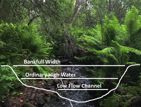
Figure 1-1. Bankfull width, ordinary high water mark, and a low flow channel on a small stream
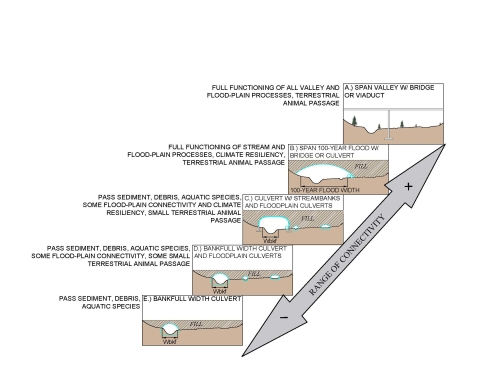
Figure 2-1. Range of crossing ecological objectives and examples of corresponding design approaches
Figure 2-2. Structure Width Decision Tree
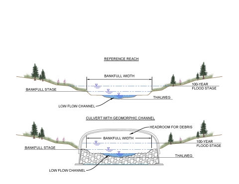
Figure 2-3. Example culvert placement relative to geomorphic channel features
Figure 2-4. Placement of floodplain culverts
Figure 2-5. Vertical adjustment potential example and factor of safety for various types of substrate
Figure 2-6. Streambank width, culvert width, and embedment depth recommendation
Figure 2-7. Two stage channel with V shaped low flow channel
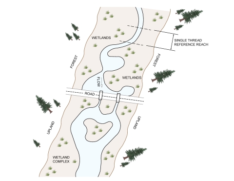
Figure 2-8. Graphical Illustration of Method A in a wetland complex
Figure 2-9. Recommendations for fish passage relative to tidal cycles
Figure 2-10. Example rock cluster or rock band layout used to stabilize the low flow channel
Figure A-1. Illustration of different entrenchment ratios
Figure A-2. Illustration of flood prone width
Figure A-3. Geomorphic processes and stream types relative to channel slope
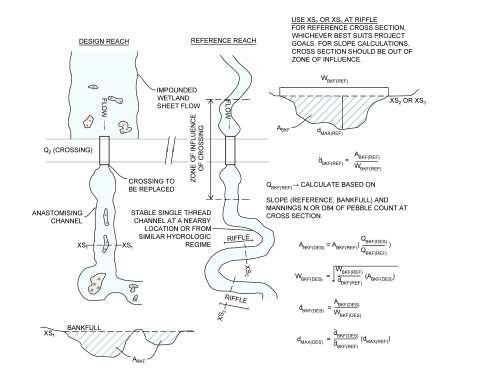
Figure A-4. Example application of the geomorphic analog method
Figure B-1. Sample Streambed Material Sizing
1. INTRODUCTION TO THE METHOD
The importance of this document lies in the understanding of ecological function in relation to stream crossings. The USFWS Alaska Fish Passage Program (AFPP) wanted to provide a reference for stream practitioners and partners that outlines the steps necessary to ensure that crossing sites are designed not only to safely route flood flows and provide for fish passage (hydraulically or biologically) but also support natural stream processes to the greatest extent possible.
Other publications commonly used for design of culverts at road stream crossing in Alaska include the United States Forest Service (USFS) stream simulation publication (USFS 2008) and a Memorandum of Agreement (MOA) between the Alaska Department of Fish and Game and the Alaska Department of Transportation and Public Facilities (ADF&G and ADOT&PF 2001). Both documents use the term “stream simulation”to describe a “nature like” design method; however, these two documents present two very different approaches to stream simulation designs. The USFS publication (USFS 2008) focuses on providing crossings that mimic sediment transport and geomorphic channel geometry up to the bankfull discharge stage for passage of all aquatic organisms while the MOA (ADF&G and ADOT&PF 2001) uses the width defined by the Ordinary High Water Mark as the primary standard for fish passage.
The AFPP has taken lesson learned from crossings constructed using the aforementioned guidelines and criteria over the last 20 years and adopted a geomorphic analog method as the basis for the guidelines presented in this document. These guidelines generally follow the USFS stream simulation approach, with some modifications. The goal of this guidance is to support ecological function and stability at stream crossing sites designed and implemented across the unique and complex Alaskan environment with the aim of creating road stream crossings that will meet the requirements of the Alaska Fishway Act (Alaska Statute §16.05.841) over a 50-to-75-year structure service life. Refer to Appendix C for a detailed comparison these guidelines with USFS (USFS 2008) and National Oceanic and Atmospheric Administration (NOAA 2022) stream simulation guidelines.
In order to design a stream crossing following any design method, a stream first needs to be classified by its geomorphic characteristics. Stream type classification allows the stream for the crossing in question to be generally characterized so that a type of crossing structure can be selected, and a self-sustaining channel type can be constructed through the structure. Buffington and Montgomery (2022) provides a review of classification systems that can be used to understand the natural channel geomorphic setting and processes.
The geomorphic analog design method is recommended for stable channels; e.g., systems that are not actively aggrading, degrading or experiencing accelerated bank erosion or lateral movement. Bridges should be used for braided channels if the flow is actively moving between braids.
Figure 1-1: Bankfull width, ordinary high water mark, and a low flow channel on a small stream.
2. DESIGNING A CROSSING
When designing an ecologically functioning crossing, there are many more things to take into consideration than hydraulic capacity and passage of a target species. This document is not meant to be all encompassing, but rather a collection of references, topics to consider, examples, and the AFPP’s specific preferences where applicable. New to this revision are recommendations to consider the impacts of extreme high and low flow events driven by and urbanization. The maximum 24-hour precipitation is projected to increase in Alaska due to climate change in most climate zones (SNAP 2024, Stewart et al. 2013) and may cause a response in channel bankfull width and peak flow events in the future. Measures recommended in these guidelines such as low substrate permeability, a well-defined low flow channel, debris passage, and sediment transport have also been shown to increase crossing resiliency in times of drought (NMFS 2022). If you are new to nature-like design, please refer to the USFS Stream Simulation Guidelines (USFS 2008) to get started.
Alaska has 40% of the freshwater resources of the United States (ADNR 2021), but less than 2% of the stream gauges to provide information about the resulting stream flows (USGS 2021). One of the goals of an ecologically functioning stream crossing is to provide passage for a wide range of species and life stages at a wide range of flows. With the low density of gauge data in Alaska, it is rare to find a stream gauge that will provide the designer with the data needed to understand the lower end of the flow regime. Data regarding species presence and their swimming abilities is often incomplete. Given these uncertainties, the surest way of providing for ecological function is to mimic the natural stream characteristics. Thus, a detailed geomorphic stream survey is necessary to gather information about the natural channel. In addition to completing a geomorphic stream survey, the designer should talk to local residents and road crews about historical flows, flashiness, the debris load, aufeis issues, sediment load, and beaver activity.
For predicting flood flows the designer should use multiple methods; regression equation predictions should be compared with the bankfull discharge obtained from the geomorphic survey and any local gauge data. LIDAR can be used to better understand flow paths and look for nearby crossing structures, but it should not replace a site visit and stream survey. Section 2.1 provides guidance on using the geomorphic survey, hydrology, and GIS data to design a crossing. For a sample step-by-step process while designing an alluvial channel crossing, refer to Section 2.2. Reference Section 2.1.5 for recommendations for wetlands, sloughs, and relic channels where a reference reach may not be available or not reflect the current flow regime.
This section will cover a variety of topics, such as: ecological functioning, culvert size, slope, and substrate; use of the reference reach; special conditions; and habitat conservation measures.
| ** Updated 1/27/2025: ** clarified that streambanks built inside culverts should be stable. |
Whenever possible, the primary structure width should be greater than the bankfull channel width to accommodate construction of stable streambanks and wildlife crossings as shown in Figure 2-1. Crossings wider than bankfull width will offer more resilience in locations where precipitation is expected to increase. Figure 2-2 provides a decision framework for choosing appropriate structures in stable, alluvial streams, with the caveats noted in section 2.1.1.2, when project funding and site constraints allow.
Figure 2-1. Range of crossing ecological objectives and examples of corresponding design approaches (adapted from USFS, 2008).
Figure 2-2. Structure width decision tree.
The entrenchment ratio (ER) and bankfull width (Wbkf) in Figure 2-2 should be derived from the reference reach geometry, ideally located upstream or downstream of the crossing. The reference reach should be located outside of the influence of the crossing or other human impacts and should not be located on an unstable reach which is downcutting, aggrading, exhibiting excessive bank erosion, or over-widened. Use the synthetic width method to determine the appropriate bankfull width for relic channels and sloughs. Figure 2-2 is not intended for low slope wetland complexes or sand bed streams; for these systems the best solution is a bridge that spans the 100-year flood width (W100)and provides connectivity for side channels. If this is not practical, a bankfull width culvert can be used on the primary channel with floodplain culverts on side channels; follow the guidance in Figure 2-4. Refer to cautions in paragraph 2.1.4.1 regarding locations with aufeis and permafrost. Structures on new roads should span the 100-year flood width (W100) to minimize disturbance to area and floodplain functions, where possible.
2.1.1.3 Debris
The goal of this guidance is to provide a crossing that will pass aquatic organisms, water AND woody debris to the extent reasonable and possible. The design should provide adequate freeboard for woody debris to pass through the structure at the 100-year flood flow (Q100).
Flows up to the bankfull stage have been shown to be responsible for forming and maintaining channel features and transporting most of the sediment in alluvial systems. By maintaining the hydraulic geometry of the channel up to the bankfull stage (Figure 2-3) we can maintain sediment transport equilibrium between the crossing and the natural channel. Ensuring sediment transport remains in equilibrium helps to ensure the substrate both within and downstream of a crossing will best support the habitat needs of aquatic species.
Figure 2-3. Example culvert placement relative to geomorphic channel features.
Culvert crossings in systems that are actively degrading, aggrading, exhibit excessive bank erosion, or exhibit excessive laterally migration, should be avoided. If they cannot be avoided, these channels must be stabilized at least on a reach-length basis to prevent headcut or excessive lateral movement prior to the construction of a new crossing structure. (Castro and Beaver, 2016)
Crossing structures should be placed within/over the pre-development natural channel alignment when possible. New road alignment should be as close to perpendicular to the channel as possible. The crossing location should also be chosen to cross at a straight riffle feature. The stream may need to be realigned at existing roads; however, avoid cutting off meander bends. Avoid placing crossing structures at pools or stream bends, including immediately downstream of meander bends. For the stable creeks that these guidelines are recommended for, lateral movement typically occurs on the order of hundreds of years (Knighton 1998), therefore it is reasonable to assume that the minimum amount of movement risk is associated with the current natural channel alignment. Additionally, putting a road crossing over a straight section of the stream generally represents the most stable lateral movement portion of the stream. If possible, we recommend not locating a crossing immediately downstream of a meander bend as they are more likely to migrate downstream and may impact the road prism when roads persist for 50 years or more. If realignment of the stream is required, we recommend mimicking the meander geometry of the reference reach and keeping the slope within 25% of the reference reach as described in Section 2.1.2.4. Refer to Chapter 6 of USFS (2008) for a discussion and preferred solutions to many typical alignment challenges.
Culverts used in stream crossings should be designed, constructed, and maintained so as to provide for ecological function of the stream, including connectivity of wetlands and riparian areas adjacent to stream channels to allow for the unrestricted movement of water, all species of fish and wildlife, nutrients, sediment, and woody debris, to the greatest extent possible. A longer span structure such as a bridge that spans the entire floodplain is the ideal solution for providing stream function, refer to Figure 2-1. If a bridge is not feasible, floodplain culverts (Figure 2-4) may also be considered to provide lateral connectivity and wetland function upstream and downstream of the crossing.
Reference reach selection recommendations may be found in Appendix A under the definition of the Geomorphic Analog Method.
Data gathered should include at a minimum: channel width at bankfull, bankfull cross-sectional area; the bankfull slope and slope ratio; substrate grain size; key pieces; stream type; bankfull average and maximum depth; low flow channel geometry; flood prone width; stream order; and watershed area (USFS 2008). The reference reach bankfull dimensions should be determined in the field by surveying a detailed cross section at the upper 1/3 of a representative riffle. See Section 2.3.
The channel in the crossing structure should not substantially differ from the reference reach condition in regards to the channel width at bankfull, bankfull and low flow channel cross-sectional area, stream type and bankfull average depth (USFS 2008).
CONSIDERATIONS FOR FLOODPLAIN CULVERTS:- FLOOD PLAIN CULVERTS CAN BE PLACED ANYWHERE IN THE FLOODPLAIN WHERE FLOWS WILL REACH THEM AT HIGHER FLOOD STAGES.
- THEY MUST BE SEPARATE VERTICALLY EITHER BY HIGH INVERT OR BY STABLE SUBSTRATE TO PREVENT THE STREAM FROM BYPASSING THROUGH THEM AT NORMAL FLOWS. VERTICAL SEPARATION IS REQUIRED TO ENSURE ADEQUATE DEPTH IN THE PRIMARY FLOW CULVERT TO ALLOW FOR FISH PASSAGE AT LOW FLOWS. THE IDEAL INVERT ELEVATION IS THE BANKFULL ELEVATION.
- THEY CAN BE EMBEDDED IF VERTICAL CONSTRAINTS OR COVER REQUIREMENTS DICTATE OR IF SMALL ANIMAL PASSAGE IS DESIRED (PROVIDE SOIL COVERAGE ALONG BOTTOM TO FACILITATE).
- WELL GRADED MATERIAL STABLE TO THE 100 YEAR FLOOD FLOW SHOULD BE USED TO DIRECT FLOWS AND PROVIDE EMBEDMENT OF FLOOD PLAIN CULVERTS. THE GOAL IS TO PREVENT WASHOUT OF THE MATERIAL AND SUBSEQUENT FLOW SPLITTING AFTER FLOOD WATERS RECEDE IF A FLOOD PLAIN CULVERT IS EMBEDDED.
- PIPE-ARCH SHAPES CAN BE USED TO DEVELOP CAPACITY EARLIER IN THE FLOOD CYCLE.
|
Figure 2-4. Placement of floodplain culverts.
2.1.2.4 Slope
The crossing slope should be within 25% of the bankfull slope of the selected reference reach. For example, if a reference reach is 1.0% slope, the minimum design slope of the stream simulation culvert would be 0.75% and the maximum design slope would be 1.25% (USFS 2008).
For the Geomorphic analog method, crossing structures should be designed to accommodate at least the 100-year flood flow (Q100) (USFS 2008). Designing for the 100-year flood is a choice we have made for projects funded by AFPP to maximize success over the long-term considering the wide margin of error in hydrologic predictions and expected life of an installation. Although the 100-year flood flow only has a 1% probability of occurring in any given year, for any 50-year period, there is a 40% chance that the 100-year flood will occur and a 64% chance that the 50-year flood will occur. Given the rather high likelihood of exceeding the design flow during the culvert lifetime, the designer should carefully consider the consequences of potential failures during flood events. While keeping in mind that many jurisdictions have minimum hydraulic standards by road type, the road owner and project funders may select a larger design flood that takes into account their tolerance for risk of failure.
Round culverts should have a minimum diameter of seven feet and full-invert box or arched culverts should have a minimum height of seven feet. Culverts should also have a minimum vertical clear distance of four feet from the constructed stream thalweg to the top of the culvert. These minimum clearance recommendations are to allow sufficient space to construct and maintain the stream channel inside the culvert. However, each site is unique and needs to be evaluated as such with the ownership and equipment available. This minimum diameter applies for small streams with a bankfull width of seven feet or less. For larger streams, a longer span structure (bridge or culvert) should be used that meets the requirements of these guidelines. A bridge should also be considered for all stream widths to provide better floodplain connectivity.
Pipes and arches should be corrugated; smooth concrete is possible, smooth wall metal or plastic pipes should not be used. This guidance is based on the need for culverts to have some frictional surface to assist in keeping substrate within them as well as having some corrugations for small fish passage along the edges in cases where no streambanks are incorporated. Conversations with hydraulic engineers and fish passage professionals over the years indicate that smooth bore pipes readily evacuate sediment adversely compared to corrugated pipes. Modeling experiences by AFPP, ADOT&PF and others also indicate that fish passable velocities are much harder to meet without some friction, particularly at slopes greater than 1%.
Round culvert pipes should have a minimum invert burial depth (measured from the thalweg) of forty percent (40%) of the culvert diameter into the substrate; box culverts and pipe arch culverts, should have a minimum invert burial depth of twenty percent (20%) of the culvert’s rise into the substrate, unless vertical adjustment potential (VAP) analysis shows less fill is acceptable (Figure 2-5). Bottomless culverts with footers need to have sufficient burial depth and armor material to protect the footings from potential scour over the life of the structure. In areas where permafrost is very close to the surface, a hybrid of the stream simulation and hydraulic method may be considered to reduce the culvert embed and prevent thaw of the permafrost. This guideline is based on discussions with Fairbanks ADOT&PF and ADF&G in what is the current practice based on their experiments in applying the ADOT&PF/ADF&G MOA and geomorphic culvert design in Arctic conditions.
DELINEATE THE LOWER VERTICAL ADJUSTMENT POTENTIAL (SCOUR) LINE.- CHOOSE DEEPEST POOL ALONG CHANNEL NOT INFLUENCED BY THE UNDERSIZED CULVERT.
- ADJUST LINE TO REFLECT SCOUR/FILL PROCESSES THAT OCCUR DURING FLOODS. RECOMMENDED CRITERIA
- 1.0 POOL MAX DEPTH (PMD): STEP-POOL CHANNELS, S> 5%, BOULDER-COBBLE BOUNDARIES.
- 1.25 X PMD: STEP-POOL CHANNELS WITH S<5%, COBBLE-GRAVEL BOUNDARIES.
- 1.50 X PMD: RIFFLES, GRAVEL-COBBLE BOUNDARIES.
- 1.75 X PMD: RIFFLES, SAND-FINE GRAVEL BOUNDARIES.
- 2.00 X PMD: RIFFLES, SAND-FINE GRAVEL BOUNDARIES.
- NO ADJUSTMENT FOR BEDROCK.
|
Figure 2-5. Vertical adjustment potential example and factor of safety for various types of substrate.
- Substrate Stability: Culvert substrate material within the crossing structure should remain dynamically stable at all flood discharges up to and including a 50-year flood flow (Q50). For culverted crossings without an adequate upstream sediment supply, the substrate material within the crossing should be designed to resist the predicted critical shear forces up to the 100-year flood. For culverts in sand bed channels sediment retention sills may be used if necessary. For culverts with slopes 6% or greater, steps and cascade features should be sized and keyed in so not to move up to the 100-year flood event, but if necessary, sills can be used to keep footer rock in place (USFS 2008). The use of sills can often be avoided by using large, stable rock. FHWA methodology has established design for dynamic stability of the culvert substrate at the design flood as a standard of good engineering practice. We maintain that in embedded culverts there is always some sediment movement into and out of the culvert if upstream sources exist but significant movement between upper and lower VAP lines should be designed to occur at the 50-year flow or higher for locations with upstream sediment sources and 100-year flow or higher at locations without sediment sources such as lake outlets. Exceptions can exist, for instance “D” type stream with multiple channels on alluvial fans, where a stream simulation approach to streambed design may be more appropriate.
Figure 2-7. Two stage channel with V-shaped low flow channel.
- Low Flow Channel: Substrate material within/under the crossing structure should incorporate a continuous low flow channel that simulates the reference reach to allow for adequate fish passage during minimum flows. We recommend using forcing features such as rock bands or rock clusters that are stable up to the 100-year flood for better persistence of the low flow channel over time. (Figure 2-10). A “V” shaped thalweg is recommended for channels with the potential for very low flow regimes to prevent aggradation and maximize fish passage during drought conditions (Figure 2-7). See Appendix A for more guidance on design of low flow channels.
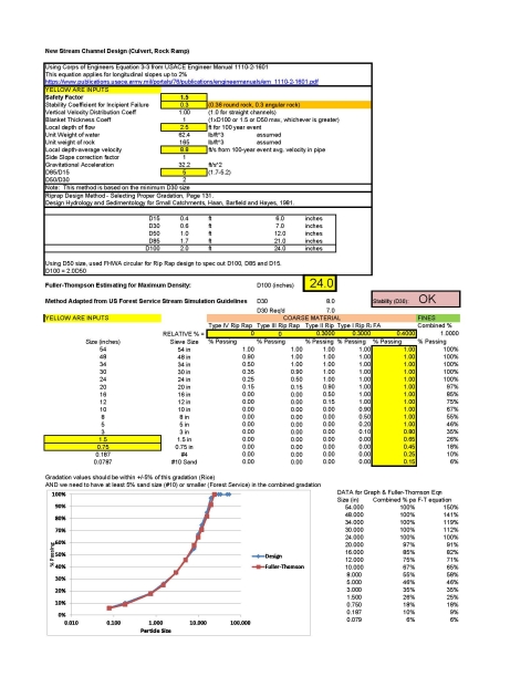
- Substrate Gradation: The gradation of the substrate material within a culvert should be designed to be a dense, well graded mixture with adequate fines to ensure that the majority of the stream flows on the surface and the minimum water depth is maintained (FHWA 2010). Refer to Figure 2-6 for a graphical illustration of this difference between a well graded and gap graded substrate. The Fuller-Thompson equation should be used to ensure a minimum void content (See Figure B-1 for example calculations). In addition, the combined gradation should have a minimum of 5% passing the #10 sieve (2 mm). (USFS 2008).
- Retention Sills: If substrate retention sills must be used (for example, sand bed systems or on slopes >6%), they should have a maximum weir height of one half (0.5) of the culvert invert burial depth (i.e. 20% of diameter for round pipes and 10% of rise for pipe arches) (USFS, 2008).Substrate retention sills should be spaced so that the maximum drop between weirs is four inches (4”). Sills should not be used without substrate. A 4” drop is the maximum perch for juvenile salmon passage per historic discussions with ADF&G in case there is complete evacuation of sand from the culvert, fish passage is technically possible until the next flood event. AFPP experience is that sills can be 1) used in step-pool or cascade environments to help hold steps in place and 2) in sand bed systems to capture sand on the receding limb of flood events for a streambed. While USFS guidance indicates that sills should be placed below the lower VAP line, we maintain that in step-pool or cascade environments, sills should be based on where the stability is needed; for a sand bedded channel, it will depend on the longitudinal surveys and minimizing headcut potential upstream. (USFS 2008)
Maximum Substrate Size: The D100 of the substrate should not exceed the bankfull width divided by 4 (Figure 2-6) (USFS 2008).
2.1.5 Special Conditions
Wetland complexes, relic channels, and sloughs pose a challenge as the geomorphic evidence often does not provide information about the current flow regime or bankfull channel. In these cases, the designer may rely on a geomorphic analog from a nearby stream or use flood frequency predictions to size the bankfull channel. Regression equations may introduce very large errors into the design process as confidence intervals for these equations may result in a full order of magnitude of potential error at the 95% confidence level (See Table 1). If the designer must use hydrologic flood flow predictions instead of a reference reach, we recommend relying on local stream gauge data to size the bankfull and low flow channels or installing a gauge and developing local information. In these challenging environments, we have installed continuous stream gauging for two to three years prior to finalizing a crossing design to better estimate the bankfull and low flow discharge.
Table 1. Example comparison between local gauge predictions and regression equation predictions for the Little Tonsina River.
| RI | Q/A Method LittleTonsina Gauge 15207800 | Q/A Method Squirrel Creek Gauge 15208100 | 2016 Regression Method | 2016 Regression 5% Lower Confidence | 2016 Regression 95% Upper Confidence |
| yr | cfs | cfs | cfs | cfs | cfs |
| 2 | 495 | 376 | 1,030 | 359 | 2,930 |
| 5 | 654 | 604 | 1,590 | 567 | 4,450 |
| 10 | 777 | 780 | 2,000 | 716 | 5,610 |
| 25 | 951 | 1,032 | 2,550 | 893 | 7,300 |
| 50 | 1,097 | 1,237 | 2,970 | 1,020 | 8,670 |
| 100 | 1,257 | 1,474 | 3,410 | 1,140 | 10,200 |
| 200 | 1,432 | 1,712 | 3,850 | 1,250 | 11,900 |
| 500 | 1,692 | 2,081 | 4,460 | 1,380 | 14,400 |
Should field geomorphic data show an existing stream in a relic channel (i.e., old glacial outwash) or slough, with no defining bankfull features, the synthetic width method may be used. See Section 2.1.5.4.
If possible, avoid crossing wetlands to minimize impacts to these important ecosystems. If they must be crossed, the ideal crossing in a wetland complex is a low or zero slope crossing that emulates the low velocity and water depth of the surrounding wetland environment yet meets flood standards on its own or with additional floodplain culverts. To develop initial widths for such a crossing, the following situational methods could be applied:
- Method A: The designer may use a reference reach upstream or downstream in a single thread portion of the creek to size the proposed crossing (Figure 2-8). Recommendations for choosing a reference reach may be found under the definition for the Geomorphic Analog Method.
Figure 2-8. Graphical Illustration of Method A in a wetland complex.
- Method B: If no reference reach is available on the same stream or if the crossing slope needs to be steeper than any reference reach on the same stream due to constraints such as road height or maintaining upstream water levels, crossing stream types should be selected using an appropriate geomorphic analog primarily based on slope in conjunction with the synthetic width method to develop the crossing structure dimensions. A geomorphic analog (Figure A-3) should be used to develop the channel geometry.
- For both Method A and Method B, floodplain culverts should be provided as conditions permit to allow for wetland continuity across the floodplain area and to minimize flow constriction at flood levels (USFS, 2008). Floodplain culverts (Figure 2-4) should be placed in the floodplain outside of the primary channel and at a higher elevation to ensure a minimum depth will be maintained in the primary crossing structure for fish passage at low flows.
2.1.5.4 Synthetic Width Method
A synthetic width may be estimated for culvert sizing by utilizing a calculated 2-year flood event with an average cross-sectional velocity of less than 4 feet per second (fps) unless there is additional supporting data or other agency criteria to design otherwise. The recommended maximum velocity of 4 fps was chosen based on the observation by Leopold(1994)that “For rivers of moderate size (2 to 100 square miles of drainage area), the flow at bankfull stage will ordinarily have a mean velocity on the order of 4 feet per second” (p. 33). Note that this method or velocity may not be applicable for all cases and the velocity would ideally be less, particularly in stream gradients of 1% or less.
Beaver barriers, trash racks, or debris interceptors should not be used because of the potential to block adult salmon without robust and regular maintenance. Bollards at least one bankfull width upstream of the culvert may be used if needed to trap debris or move beaver dam building upstream.
2.1.5.6 Tidally Influenced Culverts
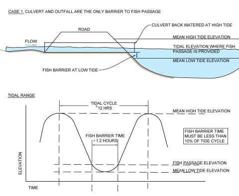
Fish passage criteria for tidally influenced culverts should be satisfied 90 percent of the time (Figure 2-9). Tidally influenced streams may sometimes be impassable due to insufficient depth at low flow and low tide. If the tidal area immediately downstream of a culvert is impassable for fish at low tide under natural conditions, the 90 percent passage criterion would apply only to the time during which fish can swim to the culvert.
Figure 2-9. Recommendations for fish passage relative to tidal cycles.
2.2 Typical Culvert Design Procedure in Alluvial Channels
The following list sequentially describes a procedure used by the USFWS Alaska Fish Passage program for Fish Passage Culvert Design in alluvial channels. It is not intended to preclude other design approaches. Whatever design approach is chosen, we do not recommend omitting any of the steps outlined in this section. We recommend consultation with the local Alaska Department of Fish and Game (ADF&G) habitat permitting office early in the design process.
2.2.1 Complete a hydrology report. If site is un-gauged try multiple flood frequency estimation methods (USGS Regression Equations, Manning’s Equation, TR-55 Method, etc.). Use LIDAR data and imagery to better understand flow paths.
2.2.2 Complete crossing survey and reference reach survey (See site survey checklist in Section 2.3). Historical imagery may also be useful for understanding how the stream has evolved over time.
2.2.3 Use channel survey data and site observations to determine the channel type and valley type at the crossing. (Buffington & Montgomery, 2022)
2.2.4 Determine the geomorphic design approach to meet the objectives of the crossing. (See Figure A-3).
2.2.5 Upload survey data and pebble count data to a computer aided design (CAD) or a spreadsheet as appropriate for analyzing the data.
2.2.6 Plot long profile and cross sections and determine bankfull width (Wbkf) of the reference cross section (typically a representative riffle).
2.2.7 Determine valley slope from CAD, GIS, or field measurements.
2.2.8 Determine reference reach slope from long pro. Look at the water surface head of riffle to head of riffle. Compare with bankfull slope and adjust bankfull calls if necessary. (Bankfull slope should match water surface slope. If it doesn’t this may indicate the bankfull calls made in the field were incorrect or that channel evolution is occurring). Make sure Wbkf of reference cross section makes sense with the other bankfull calls along the profile. (Use CAD or other graphical program for this task).
2.2.9 Determine new culvert alignment, slope, vertical adjustment potential (VAP) lines, tie in points to the existing stream thalweg and draw this in on the long pro. Reference chapter 6 of the USFS Stream Simulation Publication (USFS 2008) for considerations in choosing tie in points. Make sure new culvert design slope is within 25% of reference reach slope. Expect there may be sediment deposition upstream and/or downstream at the culvert that may need to be removed. Check actual length of culvert in CAD based on tie in points to existing thalweg, embedment depth, minimum cover depth, road width and embankment slope.
2.2.10 Determine bankfull discharge and velocity for the reference cross section based on the cross section hydraulic dimensions, bankfull slope, and Manning’s or other open channel equations. (Manning’s n should be estimated from D84 of riffle pebble count, stream type, tables, etc. and compare results of different methods. Check that average bankfull velocity is between 2.5 to 5 fps for fish streams. Check that bankfull discharge is relatively close to the 1 to 2-year flood flow predicted by hydrology assessment or gauge data.
2.2.11 Create model of the existing crossing in HY8 so the existing flood capacity can be compared with the new crossing design capacity. (Note: Other hydraulic analysis software such as HEC-RAS or other culvert design software may be used in lieu of HY8 throughout the design).
2.2.12 Model new culvert in HY8. Design flow should be 100-year flood (Q100). Check the bankfull flow as well to see if the elevation is as expected. Create tail water cross section with bankfull channel, floodplain, and low flow channel. (See Appendix A for guidance on low flow channel dimensions). Model the channel cross section inside the culvert by choosing an appropriate average embedment depth that accounts for the area blocked by fill. Or use a user generated culvert cross section to model the bankfull channel and low flow channel shape directly. Choose a culvert that passes the Q100 with HW/D =0.8 or with enough headroom to pass the expected debris during a flood. Culvert should either be bankfull width or a minimum bankfull width + 3 x D100 if streambanks are constructed inside. Designer should assume D100 and check it in next step (iterate as needed). Banks are desirable for fish passage and small mammals if feasible. USFS (2008) recommends not increasing the designed channel width to more than 1.25 x Wbkf. Slope bankfull surfaces towards the thalweg at min 5% slope both inside and outside of the culvert to avoid isolated pools that may strand fish.
2.2.13 Size coarse material. FWS has developed the “Streambed Material Sizing Analyzer.xlsx” spreadsheet using the USACE (1994) rip rap sizing equation for slopes 2% and less. (See Figure B-1 for example). Input the design flood velocity in culvert (use average velocity at a given cross section) and model flow height to determine the D30 size of the coarse material required for stability. Use HY8 water surface profile to find where the max average velocity is; which may be inlet or outlet. Determine coarse and fine aggregate gradation using Fuller Thompson equation as a target (compare in the Streambed Material Sizing Analyzer spreadsheet). The spreadsheet is set up to use the ADOT&PF rip rap sizes or to use a custom coarse aggregate gradation. Note, ADOT&PF rip rap gradations are very uniform and will need to be mixed (i.e. 33% Type I + 33% Type II + 34% Fine Aggregate) in order to achieve a well graded combined gradation. For a copy of the spreadsheet contact the AFPP. Note: Refer to FHWA (2009) for alternative methods for rip rap design.
2.2.14 Determine if there is adequate upstream sediment supply to move through the culvert. You will not have adequate sediment if the culvert is at a lake outlet, you have a wetland upstream, or a stream with a silty substrate. If there is adequate sediment supply design the culvert substrate for the 50-year (Q50) flood. If sediment supply is not adequate, design culvert substrate for Q100. Check design substrate size against the upstream reach wide pebble count (Q50) and key pieces count (Q100). If the pebble counts are showing larger material than the sizes calculated, your hydrologic estimate may be low. However, in a relic channel you may have a larger pebble count in the system than would be mobilized by the current flow regime. (Note: the USFS stream simulation method relies on sediment moving through the culvert to replenish scoured sections inside the culvert. In contrast, the USFWS modified approach is to have a minimum stability for the coarse sediment in the culvert corresponding to the Q50 flow recognizing that mobility will only occur for the fine fraction of the sediment or at flows higher than Q50. See Appendix E, USFS (2008) for further discussion of the USFS approach.
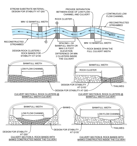
2.2.15 Design immobile key pieces and stream bank material inside the culvert for Q100. Use either rock clusters or rock bands to define the low flow channel and design for Q100. Check Q100 size against key pieces count data. See Figure 2-10 for spacing and design guidance.
Figure 2-10. Example rock cluster or rock band layout used to stabilize the low flow channel.
2.2.16 Check embed of culvert is 1.5xD100 (USFS 2008) and allows for potential scour (lower VAP, See Figure 2-5). Typical embedment depths range from 25-40% of culvert height. Also check culvert width is adequate to construct banks of 1.5xD100 per side if using banks. Will likely need to iterate to find a solution.
2.2.17 Check culvert hydraulic capacity for potential aggradation to the upper VAP line. This would be head of riffle to head of riffle and this could reduce capacity if there is a concave slope change. If there’s potential for debris flows use bankfull elevation for upper VAP instead of head of riffle. Situational awareness is key in determining the potential for debris flow. Look for landslides, old failing banks and talk to locals about the history of debris flows at the crossing.
2.2.18 Consider floodplain relief culverts where entrenchment ratio is greater than 2.0 and / or obvious side channels exist. (See Figure 2-4 and chapter 5 of USFS (2008) for guidance). Floodplain relief allows water on the floodplain to drain more quickly during flows greater than bankfull and helps to prevent aggradation of the floodplain that is common in large flood events. Floodplain relief culverts should be placed with their flow line at bankfull elevation at a minimum. (Rock stable to the Q100 may be used to infill the culvert and set the elevation of the flow line). They should not be placed at the same elevation as the thalweg of the main culvert to eliminate chance of capturing creek. Allow enough space between culverts to construct stable banks for the main culvert and not reduce the competence of the main culvert fill compaction. Use a higher Manning’s n for the floodplain relief culvert in HY8 assuming brush and grass will grow on the floodplain (Reference Arcement and Schneider (1989) for guidance on Manning’s n for floodplains).
2.2.19 Transfer design to CAD. Double check alignment, slope and tail water cross section for final culvert design and iterate if necessary.
2.2.20 Continue culvert substrate upstream and downstream of inlet and outlet for approximately 50% of Wbkf. Design substrate in constructed channel outside of culvert for Q50 or pebble count, depending on scour mitigation as flow transitions from culvert to natural channel and floodplain. If streambanks are designed in the culvert, extend rock banks outside of culvert a minimum of 2 times the D100 rock size (parallel to the flow direction) to transition to natural or bioengineered banks, depending on length of channel disturbance.
2.2.21 Design stream banks to withstand predicted velocities using appropriate bioengineering techniques. (See Fischenich (2001) for design guidance and ADF&G’s Streambank Revegetation and Protection guide (Walter, Hughes, Moore and Inoue 2005) for details commonly used in Alaska). In the long run, mature vegetation is expected to protect the banks from erosion after the temporary measure such as root wads and toe wood deteriorate. Therefore, it is important to plant and maintain vegetation until it is well established along the reconstructed banks. Vegetation should mimic stable banks in undisturbed areas of the stream.
2.2.22 Construct cross section for reconstruction of disturbed stream upstream and downstream of the culvert. The cross section should include the low flow channel, bankfull channel, and bankfull bench dimensions as well as bioengineering details. See Figure 2-3 for an illustration of typical channel, floodplain, and terrace features. Also look at floodplain width in the reference reach for guidance. If the contractor is able to disturb less streambank than anticipated, we will typically preserve undisturbed stable streambanks if possible.
2.3 Site Survey Checklist
- Use imagery and LIDAR prior to site visit if possible to select potential reference reach locations
- Call in utility locates prior to site visit.
- Walk stream and select reference reach. Reference reach should be a minimum length of 20 times the bankfull width and include at least 3 stable grade control features.
- Draw sketch maps of reference reach and road crossing.
- Road crossing: Survey longitudinal profile at least 20 times the bankfull width both upstream and downstream of the crossing, or longer if there are indications of instability or other information needs like headcut potential, debris jams, etc. The longitudinal profile should contain at least 4 stable grade control features outside of the area of influence of the existing road crossing (2 upstream and 2 downstream). If there is a slope break at the road, then 6 stable grade control features are recommended (3 upstream and 3 downstream).
- Capture OHW within the potential construction impact area upstream and downstream of culvert.
- Road crossing: Collect cross section at riffle outside of zone of influence of the crossing if possible (downstream is usually better).
- Reference reach: Flag potential bankfull indicators along length of reference reach using vegetation types, benching, and changes in substrate depositional patterns as clues. Alder and spruce are good bankfull indicator species; willows and grasses will grow below the bankfull elevation.
- Reference reach: Collect reference reach longitudinal profile data.
- Reference reach: Survey stream cross section locations in a single thread portion of the channel (recommend minimum 2 riffle cross sections and 1 pool cross section for use in road stream crossing designs; additional cross sections may be needed depending on the scope of the proposed channel restoration). Include flood plain in cross section; survey should show the floodplain width at 2x bankfull depth, if possible, for channel entrenchment calculations (or indicate if flood plain width exceeds 2.2 x bankfull width).
- Road crossing: Collect road prism and topographic survey data
- Representative Reach Pebble Count – 100 particles total. Refer to Bunte and Abt (2001) for recommended pebble count sampling methods.
- Representative Riffle Pebble Count – 1 at each riffle cross section – 100 particles each count.
- Key Piece Count (Record dimensions of the 20 largest rocks in the channel for the length of the reference reach).
Longitudinal profiles should capture major slope change in the thalweg (top of riffle, bottom of riffle, max pool depth), bankfull calls along the profile. Capture thalweg & top of water at each station. Capture bankfull elevations at all potential bankfull surfaces; an inner berm surface can easily be mistaken for a bankfull surface and vegetation is not always a reliable indicator. This allows use of other resources, such as coordination with the water surface slope and other bankfull calls along the profile, regression equation predictions, gauge data, and available regional curve data to ensure the correct bankfull cross section is selected for design. (Harman et al. (2023) provides regional curves for Interior and Western Alaska. Regional curves are currently in development in other physiographic regions in Alaska).
3. CONSTRUCTING A CROSSING
This section is both for designers considering the constructability and sustainability of their crossings, as well as construction engineers and inspectors needing a better idea of what to look out for during construction.
The designer should address the following habitat conservation measures in project specifications.
Reduce the project footprint to the maximum extent and locate associated activities in already disturbed areas or lower functioning/quality habitat, where possible
Design and reconstruct the disturbed channel upstream and downstream of the project to mimic the reference reach. Fill in scour holes and remove excess sediment in the channel deposited as a result of undersized culverts and previous crossing failures. Outside of reconstructing scour holes, banks with healthy native plants should be left intact if possible.
Specify vegetative mat with native plants that reflect typical riparian area species for the stream location along all disturbed streambanks (4’ width is typical). At least 9”, including topsoil and underlying soil layer, should be harvested for transplanting. If available mat has thinner soils, spread imported topsoil under the vegetative mat, prior to transplanting. Specify native riparian species that mimic the reference reach in disturbed riparian areas not covered by vegetative mat.
Design and specify appropriate bioengineering techniques such as root wads or toewood to protect reconstructed banks until vegetation is established.
Specify weed free gravel, weed free topsoil, and weed free erosion control materials (compost wattles or coconut fiber roll instead of straw wattles). Wash all equipment prior to mobilization to the site. Use native weed-free seed (preferably locally collected), specific to the habitat type, applied at specified rates, and cover the seed to specified depth. Consider using a tackifier, mulch, or other bonding agents to keep seed in place.
Plastic degradable netting should not be used in erosion control for any aspect of the proposed project. Prior to degradation, the netting can entangle wildlife, including amphibians, birds, and small mammals.
If using foam sheets for permafrost insulation, specify closed-cell foam rather than styrofoam insulation. Styrofoam pellets degrade water quality and break into tiny pieces creating an ingestion hazard for fish, mammals, and birds.
Avoid removing vegetation during the bird nesting season, when possible.
Consider strategically placing root wads, large logs, boulders, and slash in the riparian area after seeding, to provide topographical relief and micro-climates, and to increase the variety of plant species difficult to establish by seed (e.g., increase habitat complexity).
Pre-construction:
- Verify environmental permitting is current (e.g., USACE Section 404, DNR water use, ADFG habitat).
- Verify all necessary ROW and easements have been obtained.
- Notify local residents and businesses of construction activity and closures.
- Check that utility locates have been done.
- Check that utilities have been relocated by 3rd parties as necessary.
- Verify the stream profile has not experienced significant grade changes compared to the design profile.
- Inventory owner supplied materials and sign over to contractor.
- Check that survey monuments are located and a plan to relocate disturbed monuments is made.
- Review diversion and dewatering plan with contractor and ADFG.
- Ensure contractor has adequate pump capacity, discharge hose, correct fuel types for pumps, extra suction hose gaskets, and backup stream diversion materials. If pumping stream flows around the construction site, use screened intake for water withdrawals to avoid suction entrapment and entrainment injury to small and juvenile fish present in the area of the withdrawal.
- Confirm that the fish resource permit has been obtained and review plan for relocating fish with ADFG.
- Confirm that contractor has obtained traffic control permit if required.
- Review erosion and pollution control plan; ensure SWPPP permit obtained from ADEC if > 1 acre.
- Plastic degradable netting is not allowed for use in erosion control for any aspect of the project. Prior to degradation, the netting can entangle wildlife, including amphibians, birds, and small mammals.
- Isolate wetlands from construction-generated sediment and pollutants by maintaining a minimum 200-foot setback from waterways when storing hazardous or toxic material or refueling. Confirm that containment and cleanup materials are on site prior to starting work.
- Review the revegetation plan. Confirm source of vegetative mat. Vegetative cover should be capable of stabilizing the soil against erosion. In addition to topsoil and seed, consider transplanting willows, alder and/or spruce in the riparian area behind the vegetative mat. If rip-rap was used, backfill with finer sediments, cover with topsoil, and seed with native seed.
- Confirm and review aggregate material sources and gradations.
- Use weed free gravel, weed free topsoil, and weed free erosion control materials (compost wattles or coconut fiber roll instead of straw wattles). Wash all equipment prior to mobilization to the site. Use native weed-free seed (preferably locally collected), specific to the habitat type, applied at specified rates, and cover the seed to specified depth. Use a tackifier, mulch, or other bonding agents to keep seed in place.
- Count number of trees to be removed or already removed if a replacement ratio is specified.
- Review area of disturbance required for construction. Reduce the project footprint to the maximum extent and locate associated activities in already disturbed areas or lower functioning/quality habitat, where possible.
During construction and prior to re-watering culvert:
- Confirm culvert alignment has been staked out according to drawings and meets project objectives; notify engineer if adjustment are needed.
- Check grade elevation and slope of excavation prior to setting the culvert.
- Check top (or invert) of culvert placed at correct elevation and correct slope per drawings prior to filling with substrate.
- Prior to placement in culvert, inspect streambed infill materials at quarry or stockpile; check against design gradation, ensure enough fines are present to seal streambed during wash-in procedure.
- Check stream material is sufficiently sealed and water pools on surface prior to re-diverting the creek back into the culvert.
- Check that substrate has been sprayed down and discharge is clean and clear.
- Walk thru culvert and check substrate is firm (similar to the natural streambed).
- Discuss plan to remove diversion.
- Discuss revegetation plan and revise where necessary; save undisturbed banks if possible.
- Check channel thalweg and bank elevations at culvert inlet and outlet.
- Check channel tie in location and elevation upstream and downstream.
- For culverts with streambanks constructed inside of the culvert, check that the banks are extended outside of the culvert 2xD100 minimum and tied into natural banks.
- Check channel planform matches drawings.
- Check bankfull channel width and depth matches drawings.
- Check low flow channel width and depth matches drawings.
- Check channel dimensions upstream and downstream from culvert.
- Check rootwads or toewood constructed per plans or revise as necessary to adapt to site conditions. Check elevation of rootwads – centerline of bole at OHW or top of bole at bankfull.
During construction after re-watering culvert:
- Check embed depth of willow cuttings (min 2/3 in dirt) and trim as needed.
- Check live vegmat placed as noted on drawings.
- Check disturbed areas without vegmat have topsoil that has been track walked and seeded.
- Check revegetation matches plans and discuss required watering going forward.
- Check volume of flow in culvert matches flow upstream (not losing water in the substrate).
- Check rip rap collar placed as noted on plans.
- Check rip rap in the collar has been filled with fines.
- Verify compaction methods are adequate and meet specs during backfill of the road prism.
- Check minimum cover provided over culvert.
- Check roadway width and surface material.
- Check roadway grade.
- Check for correct installation of post-construction erosion and sediment controls.
- Re-contour slopes to blend with surrounding topography and use waterbars or contour furrowing (by track walking or manual raking- see ADOT&PF spec section 618) on steeper slopes.
- Strategically place root wads, large logs, or boulders in the riparian area after seeding, to provide topographical relief and micro-climates, and to increase the variety of plant species difficult to establish by seed (e.g., increase habitat complexity).
REFERENCES
Alaska Department of Fish and Game (ADF&G); Alaska Department of Transportation and Public Facilities (ADOT&PF) (2001). Memorandum of Agreement between the Alaska Department of Fish and Game and the Alaska Department of Transportation and Public Facilities for the Design, Permitting and Construction of Culverts for Fish Passage. Retrieved from: http://www.adfg.alaska.gov/index.cfm?adfg=fishpassage.regulations
Alaska Department of Natural Resources (ADNR) (2021), Division of Mining, Land and Water. Alaska Water Facts web page. Retrieved from: http://dnr.alaska.gov/mlw/water/
Alaska Department of Transportation and Public Facilities (ADOT&PF) (2006) Alaska Highway Drainage Manual. Retrieved from: http://dot.alaska.gov
Alaska Legal Resource Center (2008). Touch N’ Go/Bright Solutions, Inc. Retrieved from: http://www.touchngo.com/lglcntr/akstats/statutes/title41/chapter17/section950.htm
Arcement, G.J. Jr.; Schneider, V.R. (1989). Guide for Selecting Manning’s Roughness Coefficients for Natural Channels and Floodplains. U.S. GEOLOGICAL SURVEY WATER-SUPPLY PAPER 2339.
Buffington, J.M.; Montgomery, D.R. (2022). Geomorphic classification of rivers: An updated review. In: Shroder, John (Jack) F., ed. Treatise on Geomorphology (Second Edition). Academic Press. p. 1143-1190. Retrieved from: https://www.fs.usda.gov/rm/pubs_journals/2022/rmrs_2022_buffington_j001.pdf
Bunte, K.; Abt, S. R. (2001). Sampling surface and subsurface particle-size distributions in wadable gravel-and cobble-bed streams for analyses in sediment transport, hydraulics, and streambed monitoring. Gen. Tech. Rep. RMRS-GTR-74. Fort Collins, CO: U.S. Department of Agriculture, Forest Service, Rocky Mountain Research Station. 428 p.
Castro, JM, Beavers, A. Providing Aquatic Organism Passage in Vertically Unstable Streams. Water. 2016; 8(4):133. https://doi.org/10.3390/w8040133
Edwards, Pamela J.; Watson, Edward A.; Wood, Frederica. (2019). Toward a Better Understanding of Recurrence Intervals, Bankfull, and Their Importance. Journal of Contemporary Water Research & Education. 166(1): 35-45. https://doi.org/10.1111/j.1936-704x.2019.03300.x
Federal Highway Administration (FHWA) (2009). Hydraulic Engineering Circular No. 23: Bridge Scour and Stream Instability Countermeasures: Experience, Selection and Design Guidance, Third Edition, (Publication No. FHWA-NHI-09-112) Retrieved from: https://www.fhwa.dot.gov/engineering/hydraulics/library_listing.cfm
Federal Highway Administration (FHWA) (2010). Hydraulic Engineering Circular No. 26: Culvert Design for Aquatic Organism Passage, (Publication No. FHWA-HIF-11-008) Retrieved from: https://www.fhwa.dot.gov/engineering/hydraulics/library_listing.cfm
Federal Highway Administration (FHWA) (2011) Wildlife Crossing Structure Handbook, Design and Evaluation in North America, Publication No. FHWA-CFL/TD-11-003 for design of features to accommodate wildlife crossings. Retrieved from: https://www.fhwa.dot.gov/clas/ctip/wildlife_crossing_structures/
Fischenich, C. (2001). Stability Thresholds for Stream Restoration Materials, EMRRP Technical Notes Collection (ERDC TNEMRRP-SR-29), U.S. Army Engineer Research and Development Center, Vicksburg, MS. Retrieved from: http://www.spa.usace.army.mil/Portals/16/docs/civilworks/regulatory/Stream%20Information%20and%20Management/ERDC%20Stability%20Thresholds.pdf
Groenier, J.S.; Gubernick, R.A. 2010. Locating your trail bridge for longevity. Tech. Rep. 1023–2808P–MTDC. Missoula, MT: U.S. Department of Agriculture, Forest Service, Missoula Technology and Development Center. Retrieved from: https://www.fs.usda.gov/t-d/pubs/pdfpubs/pdf10232808/pdf10232808dpi300.pdf
Harman, W., Varner, M., Lamb E., and McLeod, D. 2023. Stream Design and Reclamation Guide for Interior Alaska. Bureau of Land Management. BLM Technical Report 65. Retrieved from: https://www.blm.gov/sites/default/files/docs/2023-03/BLM_AK_TR65_508.pdf
Leopold, L.B., Wolman, M.G. and Miller, J.P. (1964). “Fluvial Processes in Geomorphology.” W.H. Freeman, San Francisco, California.
Leopold, L.B. (1994). A View of the River, First Harvard University Press, Cambridge, Massachusetts
Montgomery, D. R.; Buffington, J. M (1993). Channel classification, prediction of channel response, and assessment of channel condition. Report TFW-SH10-93-002 prepared for the Washington State Timber/Fish/Wildlife Agreement. University of Washington, Seattle, WA. Retrieved from: https://gis.ess.washington.edu/grg/publications/pdfs/Channel_Report_1993.pdf
Montgomery, D. R.; Buffington, J. M (1997). Channel-reach morphology in mountain drainage basins. Geologic Society of America Bulletin 1997; 109, no. 5;596-611 Retrieved from: https://gis.ess.washington.edu/grg/publications.html#p1997
National Marine Fisheries Service (NMFS) (2022). NOAA Fisheries West Coast Region Guidance to Improve the Resilience of Fish Passage Facilities to Climate Change – 2022. NOAA Fisheries West Coast Regional Office, 1201 Northeast Lloyd, Portland, Oregon 97232. Available at: https://www.fisheries.noaa.gov/region/west-coast/
Rosgen, D.L. (1996). Applied River Morphology, Second Edition, Wildland Hydrology, Pagosa Springs, Colorado.
Scenarios Network for Alaska + Arctic Planning (SNAP) (2024). The Arctic Environmental and Engineering Data and Design Support System available at: https://uaf-snap.org/
Stewart, Brooke C.;Kunkel, Kenneth E.;Stevens, Laura E.;Sun, Liqiang;Walsh, John E.; (2013). Regional Climate Trends and Scenarios for the U.S. National Climate Assessment : Part 7. Climate of Alaska. Available at: https://repository.library.noaa.gov/view/noaa/56812
U.S. Army Corps of Engineers (USACE) (1994) Hydraulic Design of Flood Control Channels, Engineer Manual No. 1110-2-1601 Retrieved from: https://www.publications.usace.army.mil/portals/76/publications/engineermanuals/em_1110-2-1601.pdf
U.S. Geological Service (USGS)(2021) National Water Information System: Web Interface. Retrieved from: https://waterdata.usgs.gov/nwis/sw
U.S. Forest Service. (USFS)(2008). Stream Simulation: An Ecological Approach to Providing Passage for Aquatic Organisms at Road-Stream Crossings.
Walter, J.; Hughes, D.; Moore N.J.; Inoue, F. (2005). Streambank Revegetation and Protection; A Guide for Alaska. Alaska Department of Fish and Game, Division of Sportfish. Retrieved from: http://www.adfg.alaska.gov/index.cfm?adfg=streambankprotection.main
Appendix A: Description of Terms and Commentary
100-Year Flood Flow (Q100): The stream discharge that has a reoccurrence interval of 100 years, or a 1 in 100 chance of occurring in a given year; also known as the 100-year recurrence interval event. If the crossing structure is not designed to accommodate the 100-year flow, a route must be established to safely convey flows exceeding the design flow without causing damage to property, endangering human life or public health, or causing significant environmental damage. In cases of crossings within high entrenchment ratio environments (flood prone width/bankfull width >2.2) then floodplain overflow culverts may be beneficial to floodplain connectivity and can be used to pass the 100-year flood, but minimum width requirements for the primary culvert still apply.
100-Year Flood Width (W100): Wetted width of the reference reach as predicted by a 1-D or 2-D hydraulic model or by using Manning’s equation in a cross-section analyzer. Width should be calculated using the surveyed reference riffle and floodplain geometry and using Manning’s n values reflecting the channel and floodplain roughness of the reference riffle.
50-Year Flood Flow (Q50): The stream discharge that has a reoccurrence interval of 50 years, or a 1 in 50 chance of occurring in a given year.
Bankfull: For streams with entrenchment ratios greater than 2.2, bankfull is the height on the streambanks where water flow fills the channel and begins to spread out onto the floodplain. (Leopold, 1964) For streams with entrenchment ratios less than 2.2, other indicators are often required to identify the bankfull equivalent elevation such as the highest active depositional feature, slope breaks, change in particle size distribution, small benches, staining of rock, lichens, and certain riparian vegetation species (Rosgen, 1996).Use multiple indicators wherever possible to determine a common bankfull stage elevation. Where possible, calibrate field-determined bankfull stage elevation and corresponding bankfull channel dimensions to known recurrence interval discharges at gauge stations. Bankfull features are typically wider than the ordinary high water mark. Correctly identifying the bankfull channel dimensions is critical to the success of the geomorphic analog method. The design professional should pursue training in this area and use hydrologic data to verify bankfull dimensions are reasonable.
Bankfull width (Wbkf): The surface width of the stream measured at bankfull. (See Figure 1-1 for an example of bankfull width on a small stream).
Bankfull cross sectional area: The sum of products of unit width and depth at the bankfull stage elevation in a riffle cross section.
Bankfull discharge: A frequently occurring peak flow whose stage represents the incipient point of flooding. The bankfull discharge is expressed as the momentary maximum of instantaneous peak flows rather than the mean daily discharge. It is often associated with a recurrence interval of 1-2 years, with an average of 1.5 years. (Rosgen, 1996). (Note: Recurrence intervals up to decades have been found for the bankfull discharge on some streams. (Edwards et al. 2019) Stream gaging is recommended if the designer desires confidence in the bankfull discharge return interval).
Bankfull slope: The average slope through the bankfull indicators recorded at multiple locations along the longitudinal profile. The bankfull slope of a given reach should match the water surface slope measured between stable grade control features. See “Slope Ratio” term for more information on measuring the slope of a reference reach.
Dynamically Stable: Dynamic stability means that channel dimensions, slope and planform do not change radically even though they adjust to changing inputs of water, sediment, and debris. (FHWA, 2010). Dynamically stable channel features will fluctuate around a mean value but will stay within the predicted VAP lines.
D100 particle size: This corresponds to the largest particle size in a given material gradation. In other words, 100 percent of the particles in the material are smaller than the D100 size.
D84 particle size: This corresponds to the size of the particle in a material gradation such that 84 percent of the particles in the material are smaller than the D84 size.
Ecological Function: A crossing is ecologically functioning if it allows for conveyance of water, sediment, debris, marine derived nutrients, and passage of fish and other organisms in the channel, floodplain and riparian area floodplain both upstream and downstream during flows ranging from low flows during dry periods up to a 100-year flood flow. Sediment transport should remain in equilibrium throughout the range of flows so that no significant aggradation or degradation will result. In embedded culverts there is always some sediment movement into and out of the culvert if upstream sources exist. However, vertical adjustment of the channel beyond the upper and lower VAP lines should be designed to occur at the 50-year design flow or higher for locations with upstream sediment sources and 100-year or higher at locations without sediment sources such as lake outlets. Also, constructed banks should be designed for stability up to the 100-year flood flow.
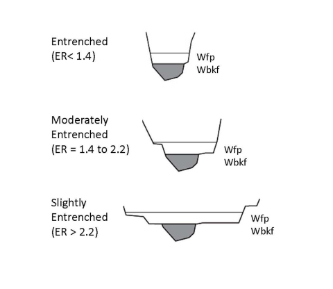
Entrenchment Ratio: The vertical containment of a river, obtained by dividing the flood-prone width by the bankfull width at a reference riffle (Groenier and Gubernick, 2010).
Flashiness: The speed of short-term changes in stream flow in response to storm events. Streams that rise and fall quickly are considered flashy and will have higher peak flows than streams that are less flashy. Impermeable surfaces, such as pavement or clay layers, will increase the flashiness of a system.
Flood-prone Area and Width: The speed of short-term changes in stream flow in response to storm events. Streams that rise and fall quickly are considered flashy and will have higher peak flows than streams that are less flashy. Impermeable surfaces, such as pavement or clay layers, will increase the flashiness of a system.
| Figure A-1: Illustration of different entrenchment ratios. (Adapted from Groenier and Gubernick, 2010). |
Geomorphic Analog Method: A geomorphic analog means that the crossing is designed using reference data from a representative section (reference reach) of the specific water body being crossed. The geomorphic analog method is a crossing design technique that attempts to replicate the natural stream channel conditions found upstream and downstream of the crossing. Sediment transport, flood and debris conveyance, and fish passage function much as they do in the natural channel if designed correctly. The geomorphic analog uses bankfull channel dimensions to size the crossing structure and channel. If there are no suitable reference reaches on the specific body of water being crossed, a reference reach may be chosen from another water body with similar geomorphic and hydrologic characteristics (Figure A-3). Refer to Buffington and Montgomery (2022) for a review of geomorphic channel classification systems.
When an appropriate reference reach is not available adjacent to the crossing site, we recommend following the criteria for selecting a reference reach:
- The reference reach bankfull width should be at least one half, but not more than two times the water body being crossed.
- The reference reach bankfull discharge should be at least one half and no more than one and one half times the bankfull discharge of the water body being crossed.
- The stream order of the reference reach should be within one stream order of the water body being crossed.
- The reference reach should be within 25% of the crossing gradient as noted in Section 2.1.2.4.
The crossing design channel width, area, and other features should be scaled to the reference reach using ratios to the bankfull dimensions (Figure A-4).
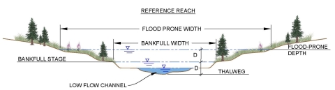
Figure A-2: Illustration of flood prone width.
Hydraulic Methods: A culvert designed with the hydraulic method is designed to maintain flow velocities to be less than the swimming abilities for the weakest swimming fish at the high fish passage flow predicted with hydrologic modeling. Due to the limitations of hydrologic modeling accuracy and the limited data on fish swimming abilities, the hydraulic method should be avoided if possible. Overall, there are very limited situations where the hydraulic method can meet the 1 fps criteria for juvenile salmon and other weak swimming fish for high fish passage flow events. Hydrology estimates and fish swimming speeds provide the basis for the success of the hydraulic design method. Yet, there are significant errors associated both with the estimation of hydrology and fish swimming speeds. We do not believe a culvert can be designed with conservative assumptions that resolve the very large margins of error common for hydrologic predictions, especially when there is no gauge data on which to base these predictions. Another problem with the Hydraulic Design method is that it is species dependent so not all fish or other aquatic organisms may be able to pass the culvert even if you are confident of your flow predictions and fish swimming abilities. The biggest concern with the Hydraulic Design method is it does not require maintenance of the geomorphic form of the channel. Mimicking the geomorphic form of the natural channel is the best way to maintain sediment transport in equilibrium because it helps to maintain the hydraulic geometry and thus the shear stresses experienced by the stream substrate at varying flow levels. Providing for sediment transport equilibrium is important both to the health of the ecosystem and the long-term maintenance and viability of a culvert as a fish passage structure.
Figure A-3: Geomorphic processes and stream types relative to channel slope (adapted with permission from Montgomery and Buffington, 1993). © Department of Geological Sciences and Quaternary Research Center, University of Washington
Low Flow Channel: A low flow channel is intended to provide fish passage at minimum flows. The low flow channel should mimic the reference reach where possible. A “V” shaped thalweg is recommended for streams that have periods of very low flow. If the low flow channel dimensions are not discernable from the reference reach, the low flow channel should have a cross section sectional area of 15-30% of the bankfull cross-sectional area and a minimum depth of four inches (4”) for small streams up to twelve inches (12”) for larger streams. The low flow channel should be defined by rock features that will resist critical shear forces up to the 100-year flood. (See Figure 1-1 for an example of a low flow channel on a small stream).
Figure A-4: Example application of the geomorphic analog method.
Ordinary High Water Mark (OHWM): OHWMis a legal, non-geomorphic term defined byAlaska statute §41.17.950 (15) which states the “ordinary high water mark means the mark along the bank or shore up to which the presence and action of tidal or non-tidal water are so common and usual, and so long continued in all ordinary years, as to leave a natural line impressed on the bank or shore and indicated by erosion, shelving, changes in soil characteristics, destruction of terrestrial vegetation, or other distinctive physical characteristics” (Alaska Legal Resource Center 2008). Reference ADF&G website for more information on identifying the OWHM. Also, see Figure 1-1 for an example of the OHWM on a small stream.
Reference Reach: A portion of a stream that represents a stable channel (dimension, pattern, profile) within the geomorphic context that exists in that segment and can represent a natural or a stable, modified condition (USFS 2008). A reference reach should be a minimum 20 times the reference bankfull width and no less than 200 feet in length for creeks less than 10 feet in bankfull width. A reference reach should also include a minimum of 4 stable grade control features. See the definition for Geomorphic Analog Method for further reference reach selection recommendations.
Retention Sills: Metal or wood plates welded or bolted into a culvert with a height of no more than one half of the embedment depth. Retention sills are intended to hold substrate in place in culverts greater than 6% slope. Retention sills should not protrude into the flow (USFS 2008).
Slope ratio: The ratio of the culvert bed slope to the upstream reach or reference reach channel slope. The slope of the reference reach should be calculated using the water surface elevations between stable grade control features at the top and bottom of the reach assuming the reach slope is consistent. To verify grade control features are accurately identified and stable, at least 4 grade control features should be included along the longitudinal profile. For stable streams without obvious grade control features use of the average water surface slope is acceptable. Unstable streams should not be used for a reference reach.
Streambanks: The streambanks correspond to the bankfull elevation of a natural channel. Streambanks inside a culvert may be simulated with large rock designed to be stable up to the 100-year flood flow.
Substrate Grain Size: A particle size distribution based on a particle count taken in the reference reach of at least 100 particles. This is also commonly referred to as a “pebble count.” Refer to Bunte and Abt (2001) for recommended sampling methods.
Synthetic Width Method: A method of calculating culvert width dimensions when the current flow regime does not coincide with the geomorphic bankfull indicators such as in a relic channel or slough or no defining bankfull features exist (See bankfull definition). The synthetic width method was developed by USFWS fish passage engineers as a design method for culvert sizing in extensive wetland environments with very low entrenchment. In many cases in these environments the bankfull width is very ill-defined, road fill height is to be minimized and velocity and substrate regime can be created to facilitate fish passage without the need to span the entire length of the wetland complex. AFPP notes this is still considered a work in progress. A description of the synthetic width method can be found under the Special Conditions, Section 2.1.5.4.
Vertical Adjustment Potential: The elevations between which the streambed might vary over the service life of the structure. Refer to Chapter 5 of USFS (2008) for a thorough explanation of the factors that should be considered when determining the vertical adjustment potential (VAP).
Appendix B: Design Aids
Figure B-1: Sample Streambed Material Sizing
Appendix C: Guidelines Comparison Table by Agency
Summary and Comparison of Agency Culvert Design Guidance and Criteria:
| Guidance Topic | USFWS: 2024 Geomorphic Analog Method | USFS: 2008 Stream Simulation Method | NOAA: 2022 Streambed simulation design method (WA, OR, ID) 2022 |
| Culvert conveyance - Design Flood | 100-year flood | Design flood - per designer or agency | 100-year-flood |
| Hydraulic Design Method | Not recommended | Not recommended | Not recommended. Requires NMFS approval. |
| HW/D ratio at design flood | 0.8 or as needed to pass debris at 100-year flood | 0.8 at design flood | Min 6 feet clearance between culvert bed and ceiling and min 1’ freeboard above the 100-year flood. |
| Culvert width | Min 1.0 x bankfull width | Min 1.0 x bankfull width + 1.0xD100 banks | Min 1.5 x bankfull width |
| Culvert Slope | Within 25% of reference reach | Within 25% of reference reach | Within 25% of reference reach |
| Embedment depth | Round - 40%; Arch & Box - 20%; or use a VAP analysis | VAP analysis to determine required embedment | 30% min, 50% max, min 3' |
| Max culvert length | No guidance | No guidance | Length / span ratio must be less than 10 |
| Smooth wall metal pipes | Do not use | Not recommended | No guidance or criteria |
| Culvert Batteries (multiple culverts installed at the same elevation) | Do not use | No specific prohibition on culvert batteries. However, min bankfull width culvert is recommended. | No guidance or criteria |
| Flood plain culverts (culverts have flow only when water reaches the bankfull or floodplain elevation) | Recommended | Recommended | Connectivity of flood plain systems is recommended by increasing the width of primary crossing structure |
| Substrate stability (for crossings with upstream sediment supply) | 50-year flood | Mimic stability of reference reach. (ie - D84 in culvert moves at same flow as D84 in reference reach). May increase particle sizes to a max of 25% larger than reference reach to account for flow constriction and increase bankfull channel width to 25% wider to reduce shear stresses in the culvert. If similar stability/mobility to upstream sediment supply is not possible, use a hybrid design method. | Must demonstrate ability to maintain substrate over life of culvert. Consider upstream sediment supply; may include large fill material for grade control and habitat. |
| Substrate stability (for crossings without upstream sediment supply) | 100-year flood | Stream simulation method does not apply | Must demonstrate ability to maintain substrate over life of culvert using stability analysis. Consider upstream sediment supply; may include large fill material for grade control and habitat. |
| Substrate retention sills | Only for >6% slope or sand bed streams, 4" max drop between sills, height limited to 50% of substrate depth | Only for >6% slope, should not project above the lower VAP line | No guidance or criteria |
| Bank stability (inside culverts) | 100-year flood | Design flood | 100-year flood |
| Forcing features for low flow channel stability (Inside culverts) | 100-year flood | Design flood | No guidance or criteria |
| Low flow channel | Yes, mimic reference reach | Yes, mimic reference reach | Yes, mimic reference reach |
| Channel hydraulic geometry | Mimic reference reach geometry | Mimic reference reach geometry | Mimic reference reach geometry |
| Check of culvert velocity versus fish swimming ability | Not required | Not required | Not required |
| Fish resting zones | Streambed roughness creates fish resting zones | Key features to mimic reference reach create fish resting zones | Larger materials provides fish resting areas |
| Revegetation | Bioengineering and revegetation with native riparian species recommended | Bioengineering and revegetation with native riparian species recommended | Re-vegetation with native riparian species recommended |
| Tidal Culvert | Passable 90% of the time | No guidance; mentioned as a special condition | No guidance |
| Trash racks | Not recommended, bollards upstream are OK | Not recommended | Prohibited except if installed above min 9” above bankfull elevation |
Updated January 27, 2025 -- Revision 10